How to creat an automatic sliding door with ardiuno and IP sensor
Automstic opening on/off of an electric circuit or electromechanical system with different type of sensor is another most come hardware programming application. We have different type of sensors for diffrent purposes. Some of them are listed below:
Types of Sensors
- Position Sensors.
- Pressure Sensors.
- Temperature Sensors.
- Force Sensors.
- Vibration Sensors.
- Piezo Sensors.
- Fluid Property Sensors.
- Humidity Sensors.
We are using IP motion sensor for today's project. IP means infared Position Sensors.
it use invisible infared rays to detect obstacle. it will send currect signer as it's reture value to the micro controller, through it's analogue GPIO pins. IP motion sensor operate on a simple principle, increase in internal circuit amps(current) by external body. Just as we can see in transistor and diod applications.
The pyroelectric elements within the housing contain electrodes made up of lead zirconium titanate ceramic materials that are capable taking temperature measurements by changing their electric charge. The sensor generates electricity from the infrared radiation or heat.
Let us start our project:
Components Details
- plastic flat sheet to design the door
- Breadboard,
- Arduino Uno,
- DVD Room Gate or linear and circular gear with dc motor,
- PIR Sensor,
- mini L298n Motor Driver,
- 330 R Resistor x 2,
- Green LED,
- Red LED,
- Male to Male jumper Wires,
- Male to Female jumper Wires,
- Female DC Power Jack,
- 5v 2Amp Power Adapter
- Relay 5v-12dc to 24v dc 1 for big motor and glass door
_ztBMuBhMHo.jpg?auto=compress%2Cformat&w=140&h=140&fit=fill&bg=ffffff)
Ardiuno uno x1
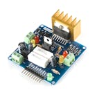
mini L298n Motor Driver
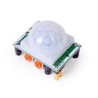
IP motion sensor
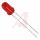
Red led 5mm
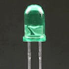
Green led 5mm
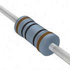
330 ohms resistor
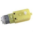
DC motor 12v
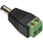
12v power pluge
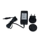
5v 2Amp Power Adapter
- Breadboard
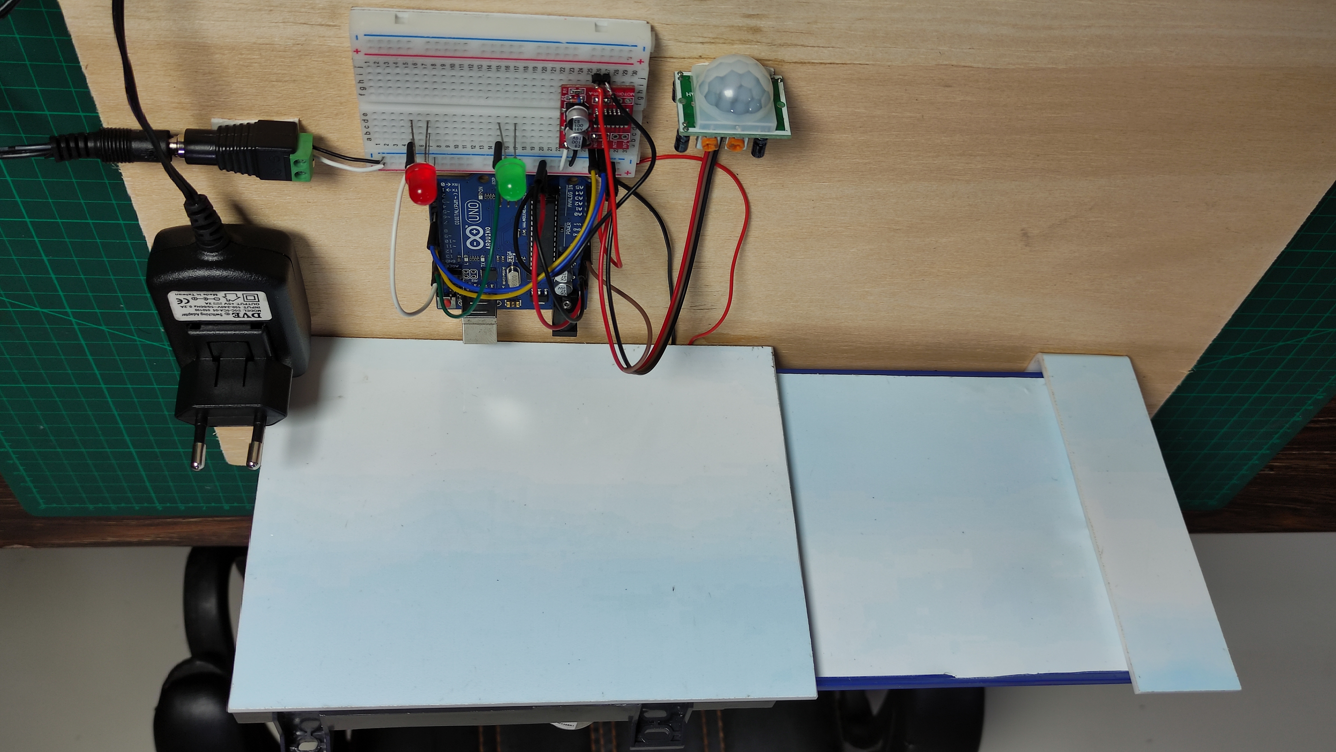
Connection:

Protous schematic
9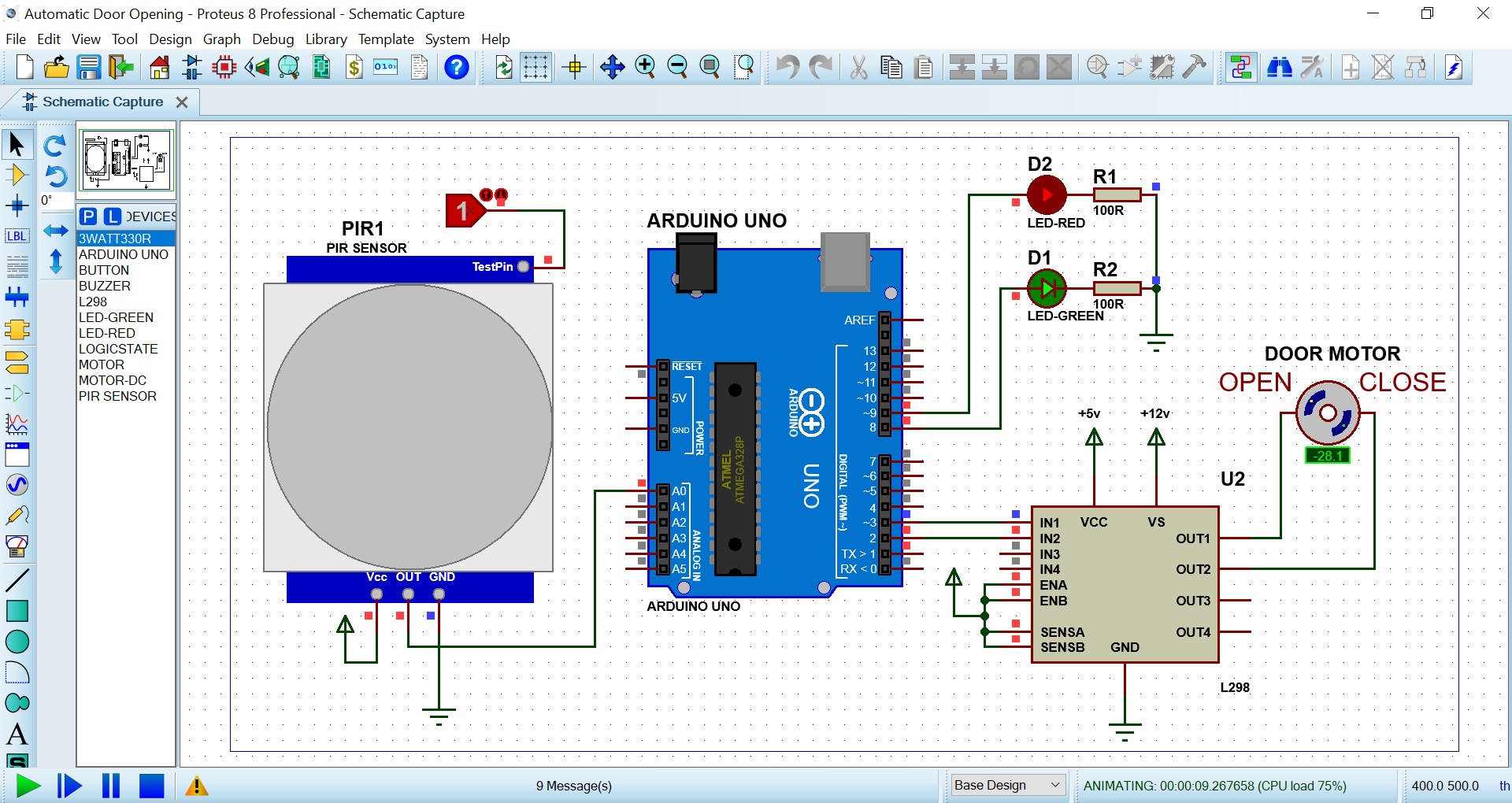
Connection:
- Connect 5v dc input to the 220v ac power supply
- Connect the 5v dc output to the the GND(negative) and V+ (positive) of the ardiuno uno board.
- Connect the Vin (center pin) of the IP sensor to the A0 (analogue pin) of the ardiuno uno
- Connect the GND(negative) and V+ (positive) of the IP sensor to the ardiuno uno
- Connect the 2 negative terminals of the Leds together and connect it to the ardiuno GND
- Connect the 2 positive terminals to 330 R resistors and connect them to GPION ardiuno degital pins (8 & 9)
- Connect the mini L298n Motor Driver to the ardiuno using it's IN 1 and IN2
- Connect the vcc and cs (5v & 12v) to the power supply
- Connect the output 1 and output 2 to the DC motor.
- Connect your ardiuno board to your PC
- Upload your code to the board using USB .
- Use DC to AC relay to drive ac motor .
Ardiuno online IDE :https://create.arduino.cc/editor/
CODE:
#define sensorPin A0 // choose the input pin (for PIR sensor)
#define G_led 8 // choose the pin for the Green Led
#define R_led 9 // choose the pin for the Red Led
#define in1 2
#define in2 3
int set_timer=5;
int sensor =0;
int seconds =0;
int flag=0;
long delay_Start;
void setup(){ // put your setup code here, to run once
Serial.begin(9600);// initialize serial communication at 9600 bits per second:
pinMode(sensorPin, INPUT); // declare sensor as input
pinMode(R_led,OUTPUT); // declare Red LED as output
pinMode(G_led,OUTPUT); // declare Green LED as output
pinMode(in1,OUTPUT);
pinMode(in2,OUTPUT);
digitalWrite(in1, LOW); // Door Open
digitalWrite(in2, HIGH);// Door Close
delay(2000); // Waiting for a while
digitalWrite(in1, LOW); // Door Open
digitalWrite(in2, LOW); // Door Close
}
void loop(){
sensor = digitalRead(sensorPin);
if(sensor==1){ // pin state change: 0 -> 1
Serial.println("Motion detected!");
digitalWrite(R_led, HIGH); // LED Turn On
digitalWrite(G_led, HIGH); // LED Turn On
if(flag==0){
digitalWrite(in1, HIGH);// Door Open
digitalWrite(in2, LOW); // Door Close
delay(2000); // Waiting for a while
digitalWrite(in1, LOW); // Door Open
digitalWrite(in2, LOW); // Door Close
}
seconds=0;
flag=1;
delay_Start = millis(); // set start time
}else{ // pin state change: 1 -> 0
Serial.println("Motion stopped!");
digitalWrite(G_led, LOW); // LED Turn Off.
}
if((flag==1) && (millis()- delay_Start) > 999){
seconds = seconds+1;
delay_Start = millis(); // set start time
}
if(seconds>set_timer){
digitalWrite(R_led, LOW); // LED Turn Off.
digitalWrite(in1, LOW); // Door Open
digitalWrite(in2, HIGH);// Door Close
delay(2000); // Waiting for a while
digitalWrite(in1, LOW); // Door Open
digitalWrite(in2, LOW); // Door Close
flag=0;
seconds=0;
}
delay(100);
}
About Me
 |
I am Akinpelu Abiodun Moses by name. I am a programmer and a graphics designer.
Follow my google website link to know more about me:
Popular Post
- Wifi hacking with python
- Complete html,css and javascript web page
- Facebook login and sign up form with html,css and javascript
- Resturant,college,hostital and pharmercy store management system with python
- online shopping website with html,css and javascript
- Text to speech app with html,css and javascript
- Online text editor with html,css and javascript
- Quiz app with html,css and javascript
- To -do app with html,css and javascript
How to creat an automatic sliding door with ardiuno and IP sensor
- Traffic light system
You can contact me for there source code on my website:


Thanks for posting this bro. Can you post watching machine code?
ReplyDeleteYes, I will post it in one of my next project. Thanks for leaving your comment ❤️
Delete